|
How Gas Turbine Work Advantages and Disadvantages of Gas Turbine Engines So why does the M-1 tank use a 1,500 horsepower gas turbine engine instead of a diesel engine? It turns out that there are two big advantages:
Gas Turbine Engineering Handbook, Third Edition How Gas Turbine Engines Work Gas turbine engines are, theoretically, extremely simple. They have 3 parts:
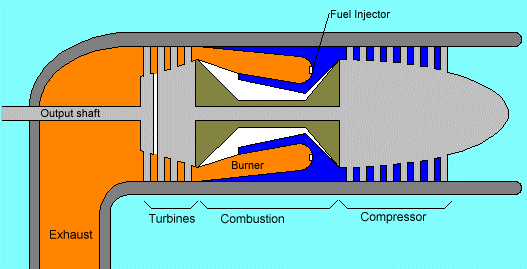
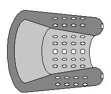
 In this engine air is sucked in from the right by the compressor. The compressor is basically a cone-shaped cylinder with small fan blades attached in rows (8 rows of blades are represented here). Assuming the light blue represents air at normal air pressure, then as the air is forced through the compression stage its pressure and velocity rise significantly. In some engines the pressure of the air can rise by a factor of 30. The high-pressure air produced by the compressor is shown in dark blue. This high-pressure air then enters the combustion area, where a ring of fuel injectors injects a steady stream of fuel. The fuel is generally kerosene, jet fuel, propane, or natural gas. If you think about how easy it is to blow a candle out, then you can see the design problem in the combustion area - entering this area is high-pressure air moving at hundreds of miles per hour. You want to keep a flame burning continuously in that environment. The piece that solves this problem is called a "flame holder", or sometimes a "can". The can is a hollow, perforated piece of heavy metal (shown here is half of the can in cross-section):
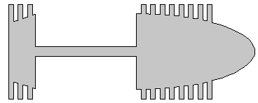
 The injectors are at the right. Compressed air enters through the perforations. Exhaust gases exit at the left. You can see in the previous figure that a second set of cylinders wraps around the inside and the outside of this perforated can, guiding the compressed intake air into the perforations. At the left of the engine is the turbine section. In this figure there are two sets of turbines. The first set directly drives the compressor. The turbines, the shaft and the compressor all turn as a single unit:  At the far left is a final turbine stage, shown here with a single set of vanes. It drives the output shaft. This final turbine stage and the output shaft are a completely stand-alone, freewheeling unit. They spin freely without any connection to the rest of the engine. And that is the amazing part about a gas turbine engine - there is enough energy in the hot gases blowing through the blades of that final output turbine to generate 1,500 horsepower and drive a 63 ton M-1 Tank! A gas turbine engine really is that simple. In the case of the turbine used in a tank or a power plant, there really is nothing to do with the exhaust gases but vent them through an exhaust pipe, as shown. Sometimes the exhaust will run through some sort of heat exchanger either to extract the heat for some other purpose or to preheat air before it enters the combustion chamber. The discussion here is obviously simplified a bit. For example, we have not discussed the areas of bearings, oiling systems, internal support structures of the engine, stator vanes and so on. All of these areas become major engineering problems because of the tremendous temperatures, pressures and spin rates inside the engine. But the basic principles described here govern all gas turbine engines and help you to understand the basic layout and operation of the engine.
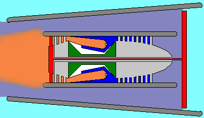
Other variations Large jetliners use what are known as turbofan engines, which are nothing more than gas turbines combined with a large fan at the front of the engine. Here's the basic (highly simplified) layout of a turbofan engine: 
You can see that the core of a turbofan is a normal gas turbine engine like the one described in the previous section. The difference is that the final turbine stage drives a shaft that makes it's way back to the front of the engine to power the fan (shown in red in this picture). This multiple concentric shaft approach, by the way, is extremely common in gas turbines. In many larger turbofans, in fact, there may be two completely separate compression stages driven by separate turbines, along with the fan turbine as shown above. All three shafts ride within one another concentrically. The purpose of the fan is to dramatically increase the amount of air moving through the engine, and therefore increase the engine's thrust. When you look into the engine of a commercial jet at the airport, what you see is this fan at the front of the engine. It is huge (on the order of 10 feet in diameter on big jets), so it can move a lot of air. The air that the fan moves is called "bypass air" (shown in purple above) because it bypasses the turbine portion of the engine and moves straight through to the back of the nacelle at high speed to provide thrust. A turboprop engine is similar to a turbofan, but instead of a fan there is a conventional propeller at the front of the engine. The output shaft connects to a gearbox to reduce the speed, and the output of the gearbox turns the propeller.
|
|